3D Design Software for Plastic Mould Manufacturing: Features, Tolerances, and Key Tools
If you want to create 3D models, test the mold’s performance, and ensure the molded pieces are precise, you’ll need plastic mold design software. It is easier to design parts, make tools, and simulate how the mold will flow with these tools. This article will talk about the three most popular 3D design programs for making plastic molds, focusing on their main features, standard tolerances, and main purposes.
1. CAD (Computer-Aided Design) Software for Plastic Molds
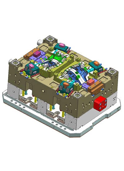
CAD software is essential for creating detailed 3D models of plastic parts and molds. These tools help designers craft precise parting surfaces, mold cavities, and tooling. Here are the most popular CAD software used in plastic mold design:
1.1 SolidWorks
- Overview: SolidWorks is one of the most widely used CAD tools for designing plastic parts and injection molds. It integrates mold design features and simulation tools that enable users to create detailed 3D models of molds and test their performance.
- Key Features:
- Mold design features (core/cavity, parting lines)
- Mold flow simulation
- Draft analysis
- Assembly design
- Default Tolerance: ±0.1mm for general parts; customizable to ±0.02mm or ±0.01mm for high-precision designs.
1.2 AutoCAD
- Overview: AutoCAD is widely used for 2D and 3D design, with common use in mold component creation and detailed design drawings. It’s more general-purpose compared to other CAD tools but still offers valuable features for mold design.
- Key Features:
- 2D drafting and 3D modeling
- Mold part creation
- Custom tool creation for core and cavity designs
- Default Tolerance: ±0.1mm, customizable to tighter tolerances (±0.01mm) for molds.
1.3 CATIA
- Overview: CATIA is a robust CAD tool used for designing complex molds in industries like automotive and aerospace. It is ideal for multi-disciplinary design and large team collaborations.
- Key Features:
- 3D parametric design
- Surface modeling
- Mold design and assembly
- Advanced simulation and optimization tools
- Default Tolerance: ±0.1mm, customizable to ±0.01mm for high-precision, complex designs.
1.4 Siemens NX (Unigraphics)
- Overview: Siemens NX is a leading CAD tool for advanced mold design and manufacturing, particularly suited for large-scale industries like automotive and aerospace.
- Key Features:
- Advanced 3D design tools
- Mold flow simulation and cooling analysis
- Tooling design and manufacturing support
- Default Tolerance: ±0.1mm, customizable to ±0.01mm for precision molds.
1.5 PTC Creo
- Overview: PTC Creo is a powerful CAD tool offering parametric modeling and advanced surface modeling. It’s ideal for designing both plastic parts and molds.
- Key Features:
- Mold flow analysis
- Core, cavity, and runner system design
- Parametric design and assembly
- Default Tolerance: ±0.1mm, customizable to ±0.01mm for high-precision applications.
2. Mold Simulation Software
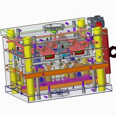
Mold simulation software helps designers test the flow, cooling, and performance of molds before actual production. These tools simulate the injection molding process to optimize design, minimize defects, and predict material behavior.
2.1 Moldflow (Autodesk)
- Overview: Autodesk Moldflow specializes in mold simulation, helping engineers optimize mold designs to improve performance and minimize defects in the injection molding process.
- Key Features:
- Mold filling simulation
- Warping and cooling system analysis
- Gate location and runner design
- Default Tolerance: ±0.1mm for general simulation; customizable for shrinkage and distortion to ±0.02mm.
2.2 Simpoe-Mold
- Overview: Simpoe-Mold is a user-friendly mold flow simulation software, widely used for early-stage design validation and optimization.
- Key Features:
- Injection molding simulation
- Filling, packing, and cooling analysis
- Cycle time and cost estimation
- Default Tolerance: ±0.1mm, adjustable for specific design needs.
2.3 SIGMA Plastic Services
- Overview: SIGMA Plastic Services offers design and simulation tools that help engineers understand plastic flow, cooling, and stress distribution within molds.
- Key Features:
- Stress analysis
- Cooling efficiency analysis
- Plastic injection simulation
- Default Tolerance: ±0.1mm, customizable for simulation accuracy.
3. Mold Design and Tooling Software
Mold design and tooling software help create the physical tools required to produce molds, including core and cavity designs, parting lines, and draft angles.
3.1 TEMA (Mold Design)
- Overview: TEMA is a comprehensive software suite used for designing the tooling required for plastic injection molds, focusing on mold base design and mold construction.
- Key Features:
- Core and cavity design
- Draft angle and parting line analysis
- Mold base design
- Default Tolerance: Customizable based on design complexity, typically ±0.1mm for general use.
3.2 Moldex3D
- Overview: Moldex3D is a CAE-based software specialized in 3D injection molding simulation, helping optimize mold designs and molding processes.
- Key Features:
- Flow and cooling simulation
- Gate location optimization
- Shrinkage and warpage prediction
- Cycle time optimization
Default Tolerance: ±0.1mm, adjustable to ±0.02mm for precision designs.
3.3 eDrawings (SolidWorks)
-
- Overview: eDrawings works alongside SolidWorks to create interactive 3D models of plastic molds. It’s ideal for real-time collaboration and visualization.
Key Features:
- Interactive 3D model sharing
- Mold part and tool design
- Real-time collaboration tools
- Default Tolerance: ±0.1mm, customizable based on part complexity.
4. CAM (Computer-Aided Manufacturing) Software for Molds
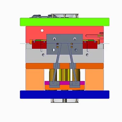
CAM software is used to generate tool paths and machining instructions from 3D models, enabling precise mold manufacturing.
4.1 Mastercam
- Overview: Mastercam is a leading CAM software used for designing tooling and machining processes required to create molds. It generates CNC toolpaths based on the 3D model.
- Key Features:
- CNC toolpath generation
- 3D milling and turning
- Mold tool creation
- Default Tolerance: Customizable based on machining requirements, typically ±0.1mm.
4.2 Edgecam
- Overview: Edgecam provides CAM solutions for mold makers, focusing on CNC programming for injection mold manufacturing and toolpath generation.
- Key Features:
- CNC programming for injection mold manufacturing
- 3D toolpath simulation
- Automation of mold creation
- Default Tolerance: ±0.1mm, adjustable for precision machining.
4.3 Delcam PowerMILL
- Overview: PowerMILL is a high-performance CAM software used for advanced machining, particularly for 3-axis, 4-axis, and 5-axis machining in mold making.
- Key Features:
- Advanced machining strategies
- High-speed machining
- Simulation of toolpaths
- Default Tolerance: Customizable for tight tolerances based on machining precision.
5. 3D Printing Software for Mold Prototyping
3D printing software is often used for prototyping molds and testing designs before committing to full-scale manufacturing.
5.1 Rhino
- Overview: Rhino is popular for rapid prototyping and mold design, known for its flexibility in modeling complex shapes and forms.
- Key Features:
- Freeform surface modeling
- Rapid prototyping
- Mold flow analysis integration
- Default Tolerance: ±0.1mm, customizable based on prototyping requirements.
5.2 Fusion 360 (Autodesk)
- Overview: Fusion 360 integrates CAD, CAM, and CAE into a single platform. It’s used for both mold design and prototyping, offering cloud-based collaboration.
- Key Features:
- Cloud-based collaboration
- CAM integration
- Mold design and testing features
- Default Tolerance: ±0.1mm, customizable to ±0.01mm for high-precision parts.


