


Molding Clear Plastic at DSW
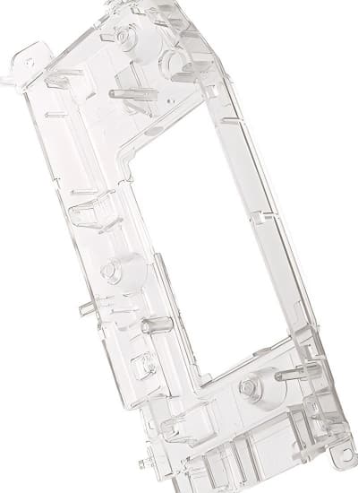
Transparent plastic molding is widely used in consumer goods like clear containers and packaging, medical devices such as syringes, automotive parts like automotive lighting and instrument panels, and electronics for device covers. It also serves in lighting fixtures, retail displays, and optical components like lenses. Additionally, it is ideal for aquariums and display cases, showcasing items with clarity. These applications benefit from the material’s durability, lightweight nature, and impact resistance, making it suitable across various industries. However, producing these transparent components requires greater precision compared to standard injection molding.
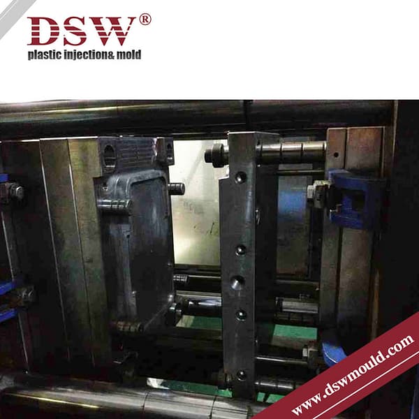
At DSW, we offer high-quality, cost-effective custom clear plastic molding solutions. The foundation of a superior transparent plastic part is a well-designed, high-precision mold, and we ensure that our injection molds meet the highest standards for quality and accuracy.
Choosing the Right Transparent Plastic for Your Project
When selecting a transparent plastic for your product, it’s essential to consider factors like durability, clarity, cost, and resistance to environmental factors such as UV light or chemicals. Here’s a quick comparison of the five plastics:
PC: Best for high-impact, durable applications where strength and transparency are critical.
PMMA: Ideal for glass-like applications requiring high optical clarity and UV resistance.
PVC: Suited for cost-effective, transparent applications with good chemical resistance.
PS: Best for disposable items and short-term use products where low cost is essential.
GPPS: Offers superior clarity for rigid, low-cost products that do not need to withstand high impact.
Each plastic has its strengths and is tailored to specific applications. Whether you’re developing products for the automotive, medical, or consumer goods industry, choosing the right material will ensure optimal performance and cost-effectiveness.

1. Polycarbonate (PC)
Polycarbonate (PC) is a highly durable, transparent plastic known for its impact resistance and toughness. It’s often used when both clarity and strength are essential. PC is lightweight, has excellent optical properties, and offers high heat resistance.

Key Properties:
- Impact resistance
- High transparency and optical clarity
- Good heat resistance
- Flame retardant and self-extinguishing
- Easily moldable and can be processed into complex shapes
Applications:
- Automotive lighting components
- Eyewear lenses
- Protective helmets and shields
- Medical devices
- Electronic display screens
PC is commonly chosen for applications where safety and durability are paramount, making it a go-to material for products that need both strength and transparency.
2. Polymethyl Methacrylate (PMMA)
Also known as acrylic, PMMA is a transparent plastic that offers excellent light transmittance and UV resistance. PMMA is often considered an alternative to glass due to its clarity, lightweight nature, and ability to resist shattering.

Key Properties:
- High optical clarity (transmits up to 92% of visible light)
- UV resistance
- Weather resistance
- Lightweight and shatterproof
- Scratch resistance (though less than glass)
Applications:
- Lenses (automotive, cameras, and eyeglasses)
- Aquariums and windows
- Signage and display cases
- Medical devices and dental products
- Skylights and light fixtures
PMMA is an excellent material for outdoor applications, where exposure to UV light is a concern, as well as for products requiring a sleek, glass-like appearance.
3. Polyvinyl Chloride (PVC)
Polyvinyl Chloride (PVC) is a widely used plastic with excellent transparency in its unplasticized form (uPVC). While PVC is known for its versatility and cost-effectiveness, its rigid, transparent form is ideal for various packaging and construction applications.

Key Properties:
- High clarity and transparency
- Good chemical resistance
- Fire-resistant
- Excellent strength-to-weight ratio
- Cost-effective
Applications:
- Transparent packaging materials
- Medical tubing and containers
- Clear signage and displays
- Credit cards and ID cards
- Window frames and roofing panels
PVC’s ability to maintain clarity while offering strength makes it suitable for industrial applications and products requiring visibility and durability.
Choosing the Right Steel for Clear Plastic Molding
When it comes to clear plastic molding, selecting the right steel for mold building is crucial to ensuring durability, precision, and high performance. At DSW, we use a variety of top-grade steels like NAK80, 1.2344ESR, S136, and S-STAR to meet different production needs. Whether you’re manufacturing small-batch transparent parts or large-scale products, the choice of steel directly affects the quality and lifespan of your molds.
NAK80: Ideal for Medium-Volume Production
NAK80 is a pre-hardened steel known for its high dimensional stability and excellent polishing capabilities. Its resistance to corrosion and good discharge processability make it perfect for injection moulding simple yet high-performance parts, such as car fascia boards or printer plastic covers. NAK80 is well-suited for plastics that are difficult to process, like POM and PVC, making it a top choice for medium-volume production runs.

- Advantages:
- No need for heat treatment
- Supports up to 300,000 mold cycles
- Excellent for precision products with mirror finishes
- Applications: Automotive parts, printer components, and products using corrosive plastics.
SUS420J2( S-STAR from Daido): The Best for Low-Volume, High-Polish Molds
S-STAR steel stands out for its high purity and excellent mirror polish capabilities. Its resistance to both corrosion and wear makes it ideal for manufacturing transparent plastic products like lenses and medical containers. Additionally, this steel is suitable for plastics containing flame retardants or other harsh additives.

- Advantages:
- High resistance to corrosion and wear
- Suitable for transparent plastics like PC and PMMA
- Ideal for low-to-medium volume production
- Applications: Injection molds for high-clarity plastics, as well as food industry components that require corrosion resistance.
1.2344ESR (Groditz): The Ultimate in Toughness and Wear Resistance
For projects that require extreme durability, 1.2344ESR steel is known for its high toughness and wear resistance at both high and low temperatures. It provides excellent mirror polish and machinability, making it suitable for both small and large production volumes.

- Advantages:
- Exceptional toughness and plasticity
- High wear resistance, even at extreme temperatures
- Uniform structure for consistent performance
- Applications: High-toughness injection molds for large-scale production or components requiring high durability.
P20HH (Finkl): Cost-Effective, Pre-Hardened Steel
P20HH is a versatile and cost-effective option for clear plastic molding. It offers good polishing performance and is typically pre-hardened, eliminating the need for post-production heat treatment. Its ease of processing makes it a popular choice for molds that require a smooth finish without the risk of deformation during production.

- Advantages:
- Pre-hardened for immediate use
- Good surface polishing properties
- Suitable for medium-duty molds
- Applications: Molds for mid-volume production runs, especially for clear plastic parts that don’t require extreme durability.
Molding Gate Design for Clear Parts
When designing molds for clear plastic parts, there are several gate types to consider, including hot nozzle needle valve gates, sub gates, and side-feeding fan gates. Each has its advantages and applications depending on the product’s size, thickness, and specific requirements.
1. Hot Sprue Valve Gate
A hot sprue valve gate offers excellent flow and allows a high degree of positioning flexibility, with smaller gate sizes. It’s ideal for thicker or larger clear plastic products where there isn’t an ideal spot for gating. However, it does leave a gating trace. This type of gate is commonly used in car taillights.

2. Sub Gate
Sub gates can be designed in various areas, such as mold ribs, sidewalls, or ejectors. This flexibility in gate placement allows for automatic separation from the part, leaving only slight gate marks. However, there is a tendency for material to pull out at the gate point, which can create surface pits and leave drying marks. This may require additional cleaning or polishing.

3. Side-Feeding Fan Gate
A side-feeding fan gate distributes molten plastic evenly and reduces the chances of air entering the cavity, helping to prevent streaks and bubbles. The downside is that the gate doesn’t automatically separate from the part, leaving sprue marks that need to be trimmed. This type of gate is commonly used for clear plastics like PC and PMMA, as it helps improve flow lines, and reduces jetting and flow marks. When designing fan gates, it’s recommended to place the gate in a less visible area based on assembly requirements.

Demolding Draft for Clear Parts
Clear plastic parts are more prone to scratching, so their demolding drafts need to be larger than those of regular plastic parts. The draft angle should also account for the material and wall thickness, with more shrinkage requiring a larger draft.
PC (Polycarbonate): Known for its high viscosity and strong holding force, PC is more prone to scratching, so a draft angle of 1.5° to 2° is recommended.
PMMA (Acrylic) and GPPS: Both of these materials are high in viscosity and prone to brittleness, so a draft angle of no less than 2° is advised.
Ejection Methods for Clear Parts
Clear plastic parts require careful ejection methods to avoid damaging their surfaces. Here are some common ejection systems used for clear parts:
1. Scrap Ejector
This method is used when ejecting marks on the product surface are unacceptable. The scrap ejector assists with ejecting the part without leaving any visible marks, though the scrap ejecting position may need to be trimmed afterward.
2. Slide and Ejector Bar
For products that don’t require a flawless appearance, a slide or ejector bar can be used. While these methods may leave parting line marks, they are acceptable for areas that aren’t visible after assembly.
3. Blade Ejector
Blade ejectors are ideal for products with multiple ribs or high holding forces that require no surface marks. Placing the blade ejector at the bottom of the ribs ensures even stress distribution during ejection. To avoid mold burrs, the blade ejector hole should be processed with precision cutting. If the hole isn’t smooth, it can cause damage or burning during production.
Thickness Requirements for Clear Parts
Excessive thickness in clear parts can lead to defects such as shrinkage marks, air bubbles, and swash marks, all of which compromise product quality. Thicker parts also demand higher injection pressure and longer cooling times, extending production cycles. For optimal performance, the recommended thickness for clear parts is between 1.5mm and 3mm. The ratio of length to width should be carefully managed to avoid pressure imbalances during injection, which can introduce internal stress and deformation.
| Plastic Material | Minimum Wall Thickness | Small-Sized Part Wall Thickness | Medium-Sized Part Wall Thickness | Large-Sized Part Wall Thickness |
|---|
| PC (Polycarbonate) | 0.95 mm | 1.8 mm | 2.3 mm | 3.0–4.5 mm |
| PMMA (Acrylic) | 0.80 mm | 1.5 mm | 2.2 mm | 4.0–6.5 mm |
| GPPS (Polystyrene) | 0.75 mm | 1.25 mm | 1.6 mm | 3.2–5.4 mm |
| PVC (Polyvinyl Chloride) | 1.15 mm | 1.0 mm | 1.8 mm | 3.2–5.8 mm |
To mitigate deformation, it’s important to control the injection pressure, pressure holding time, and cooling process. If adjusting molding parameters doesn’t resolve the issue, optimizing water flow through the mold can help balance cooling temperatures between the cavity and core, reducing deformation.
Injection Molding Guidelines for Clear Plastics
Producing high-quality clear plastic parts requires strict attention to design, material selection, and the injection molding process to achieve the desired level of light transmittance and surface clarity. Any defects such as streaks, porosity, whitening, pits, or discoloration can severely affect the final product. To ensure optimal results, special care must be taken throughout the process, particularly when dealing with high-melting-point, low-flowability plastics like PC (Polycarbonate) and PMMA (Acrylic).
Key Considerations for Injection Molding Clear Plastics:
- Material Selection & Preparation:
- Ensure raw materials are of high purity, with no contaminants.
- Dry materials properly using a dehumidified hopper to prevent moisture-related defects.
- Use screw cleaners before and after runs to prevent contamination.
- Process Adjustments:
- Higher Injection Temperature & Pressure: Clear plastics typically require elevated temperatures and pressures to ensure proper mold filling without causing internal stress.
- Precise Mold Design: Mold stability and finish are critical. Ensure that the runner and gate designs minimize resistance to flow to avoid defects such as flow marks.
- Controlled Cooling: Proper cooling times are essential to avoid internal stresses and to improve optical clarity.
Inspection Criteria for Clear Plastic Parts:
After production, parts should undergo a thorough inspection to ensure they meet quality standards. Key checks include:
- Surface Defects: Inspect for streaks, black spots, bubbles, scratches, and flow lines. These affect both aesthetics and performance.
- Dimensional Accuracy: Verify that dimensions fall within the specified tolerances.
- Part Integrity: Check for deformation, joint lines, or other structural issues like sink marks or warping.
- Visual Clarity: Ensure that the surface finish is free from blurring, pits, or poor gloss that can reduce transparency.
Perform these checks on at least three sample parts from each production batch to ensure consistency.

| Inspect Items | Level A Standards | Level B Standards | Level C Standards | Notes |
| Transparency | Can’t tell by eye | Allow slight deviation around upper and lower limit | Allow deviation in a relatively large range | Make boundary samples (limit samples) for reference |
| Greasy Dirt | No greasy dirt or sundries on surface | Slight dirt, acreage < 0.5mm² | Acreage < 1mm² and does not affect function | Make boundary samples (limit samples) for reference |
| Shrinkage Marks | No shrinkage marks | Slight shrinkage with small acreage | Does not affect part assembly or function | Make boundary samples (limit samples) for reference |
| Gas Marks | No gas marks | Not obvious, small acreage | Not obvious, small acreage | Make boundary samples (limit samples) for reference |
| Gate Point | +/- 0.1mm | +/- 0.3mm | +/- 0.5mm | |
| Transformation | < 0.1mm | < 0.2mm | < 0.5mm | Make boundary samples (limit samples) for reference |
| Flash | Cutting marks ≤ 0.3mm, height < 0.05mm, no flash | Cutting marks ≤ 0.3mm, height < 0.1mm, no flash | Cutting marks ≤ 0.5mm, height < 0.03mm | Make boundary samples (limit samples) for reference |
| Short Shot | No short shot | Does not affect assembly, allow slight material | Does not affect assembly or function | Make boundary samples (limit samples) for reference |
| Tolerance | Within +/- 0.05mm | Within +/- 0.2mm | Within +/- 0.5mm |
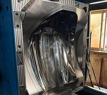
Mold Surface Finish
Clear plastic parts demand highly polished mold surfaces to achieve optical clarity. Any imperfections, scratches, or roughness on the mold surface will be transferred to the part, affecting its appearance and transparency. Molds must be polished to a mirror finish (SPI A1 standard is often required) to ensure flawless surface quality.
Common Defects and Solutions in Transparent Injection Molding
In injection molding of clear parts, several defects can arise, impacting the quality and appearance of the final product. Common issues include streaks, bubbles, poor surface gloss, whitening, and joint lines. By understanding the causes and applying targeted solutions—such as adjusting resin temperature, pressure, and mold design—you can enhance product quality and reduce production defects.

Streaks: Streaks occur during the filling and condensation processes due to internal stress acting in different directions. Vertical stress causes variations in resin fluidity, leading to a difference in refractive index, which results in flashy marks on the part. If left unchecked, these streaks can eventually cause cracks.
Solution:
- Clean grease pits thoroughly.
- Fully dry the resin.
- Reduce and control the resin temperature.
- Increase injection pressure and adjust counter-pressure.
- Lower the screw speed.
- Design appropriate gate sizes and positions.
- Improve venting size and placement.
- Ensure that nozzles, runners, and gate locations are not blocked.

Bubbles: Bubbles form when trapped air or gases can’t escape during molding or cooling. In clear plastic, this happens when air pockets are trapped in the molten plastic, affecting the product’s appearance, strength, and performance.
Solution:
- Fully dry the raw material.
- Lower the resin temperature.
- Increase injection pressure, speed, and time.
- Increase the wall thickness at the gate point.
- Adjust the mold temperature appropriately.
- Extend cooling time and improve the venting system.
- Inspect nozzles, runners, and gate locations for blockages.

Poor Surface Gloss: Poor gloss is often caused by excessive roughness on the mold surface or early cooling, which prevents the resin from replicating the mold’s surface accurately. This results in an uneven product surface with sags and crests, leading to a lack of gloss.
Solution:
- Increase resin temperature.
- Increase injection speed and time.
- Design a more appropriate gating system.
- Raise mold temperature and extend cooling time.

Whitening: Whitening often occurs due to dust contamination in the raw material or excessive moisture content in the resin.
Solution:
- Remove impurities and contaminants.
- Lower and control the resin temperature.
- Increase injection pressure.
- Shorten production lead time.
- Adjust counter-pressure.
- Raise mold temperature.

Joint Lines: Joint lines form when two or more resin streams meet, particularly at gate points. These lines create areas of increased thickness, particularly in holes, nested areas, and jointed regions.
Solution:
- Modify the product’s thickness.
- Adjust the location of the joint lines.
- Add spew wells to improve flow.
- Relocate joint lines to less visible areas by controlling flow speed using a needle valve sequence or by changing gate locations.
- Adjust the product design to eliminate joint lines.
- Increase resin and mold temperatures, as well as injection speed and pressure.

6. Sink Marks:
Sink marks occur when thicker areas of the part cool and solidify slower than thinner areas, causing depressions or “sinks” on the surface. This can happen when the cooling rate is uneven or when the packing pressure is insufficient.
Solution:
- Increase packing pressure to ensure uniform filling.
- Optimize the cooling system to promote even cooling across the part.
- Reduce the thickness of the part where possible.
- Adjust the mold design to include more uniform wall thickness.
- Increase holding time during the injection process.

7. Warping:
Warping is caused by uneven cooling or internal stresses in the material, leading to distortion or bending of the part. This can occur due to inconsistent wall thickness or improper cooling times.
Solution:
- Ensure uniform wall thickness across the part.
- Optimize the cooling system for consistent heat removal.
- Adjust mold temperature to balance cooling rates.
- Increase the holding and cooling times to allow the part to solidify evenly.
- Modify the part design to avoid sharp corners or areas prone to warping.
8. Flow Marks (Flow Lines):
Flow marks are wavy lines or patterns on the surface of the part, caused by the irregular flow of molten resin in the mold. They typically occur due to differences in cooling rates or variations in flow speed.
Solution:
- Increase injection speed and pressure to ensure smoother material flow.
- Optimize gate design and position for better material distribution.
- Increase mold temperature to improve resin flow.
- Reduce the sharp transitions in part geometry that cause flow disturbances.
- Use a material with better flow properties if necessary.
9. Flash:
Flash occurs when excess material flows out of the mold cavity and solidifies along the edges or parting line. This is often caused by improper clamping force or worn mold components.
Solution:
- Ensure the mold is properly aligned and maintained.
- Increase clamping force to prevent material from leaking out of the mold.
- Reduce injection pressure if it’s too high.
- Inspect and repair any worn-out or damaged mold parts.
- Ensure that the mold cavity is designed with tight tolerances to avoid gaps.
10. Burn Marks:
Burn marks appear as black or dark spots on the surface of the transparent part, typically caused by trapped air that overheats during injection or when the resin degrades due to excessive heat.
Solution:
- Improve the venting system to allow trapped air to escape.
- Reduce the injection speed to minimize air entrapment.
- Lower the barrel temperature to prevent resin degradation.
- Ensure proper mold maintenance to avoid wear that leads to air pockets.
11. Splay (Silver Streaks):
Splay, also known as silver streaks, is a defect that appears as silver or white streaks on the surface of the clear part. It is often caused by moisture in the resin or improper material handling.
Solution:
- Thoroughly dry the resin before molding.
- Use proper material storage and handling to avoid moisture absorption.
- Reduce the barrel temperature to prevent moisture from evaporating too quickly.
- Inspect the mold for contamination or venting issues.
12. Burning or Scorching:
Burning or scorching happens when resin degrades due to excessive temperatures, friction, or trapped gases, causing charred areas on the part.
Solution:
- Reduce injection speed to lower the shear stress on the material.
- Check and clean the venting system to prevent gas buildup.
- Lower the barrel and mold temperatures to prevent overheating.
- Increase mold cooling time to allow heat to dissipate properly.
13. Short Shots:
A short shot occurs in the clear plastic part when the mold cavity is not completely filled, resulting in incomplete parts. This is often due to insufficient material, low injection pressure, or blocked gates.
Solution:
- Increase injection pressure and speed.
- Ensure the mold is properly vented to avoid air traps.
- Check and clean the gates, runners, and nozzles to prevent blockages.
- Increase the amount of resin used in each shot.
- Adjust mold and melt temperature to improve flow.
By addressing these defects and implementing the suggested solutions, you can improve the quality of clear parts in injection molding. Proper maintenance, monitoring, and adjustments during the molding process are key to avoiding these issues.

